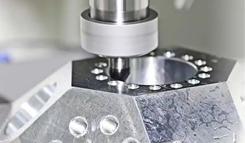
Inconsistent part dimensions can derail production, causing assembly failures, wasted resources, and costly delays. The root cause? Poorly managed CNC machining tolerances. This guide simplifies tolerance fundamentals, standards, and best practices to ensure precision and efficiency in your projects.
CNC machining tolerances define the allowable variation in a part’s dimensions. They ensure functionality, interchangeability, and quality. Standard machining tolerances depend on material, design complexity, and machining methods, with tighter tolerances increasing costs. Geometric Dimensioning and Tolerancing (GD&T) further refines precision.
Keep reading to master tolerancing for flawless manufacturing outcomes.
What Is Tolerance in Machining?
Tolerance in machining refers to the permissible limit of variation in a physical dimension of a manufactured part. It ensures parts fit and function correctly within assemblies. For example, a shaft diameter might be specified as 10 mm ±0.05 mm, meaning the acceptable range is 9.95–10.05 mm.
Types of Tolerances
- Bilateral Tolerances: Allow variation in both directions (e.g., ±0.1 mm).
- Unilateral Tolerances: Restrict variation to one direction (e.g., +0.2 mm/−0.0 mm).
- Geometric Tolerances: Control form, orientation, or position (e.g., flatness, concentricity).
Why Tolerances Matter
- Interchangeability: Parts must fit even if produced in different batches.
- Cost Efficiency: Tighter tolerances require advanced tools and longer cycle times.
- Performance: Critical for high-stress applications like aerospace or medical devices.
A machining tolerance chart helps visualize standard ranges for features like holes, threads, and surface finishes. Typical machining tolerances for CNC range from ±0.1 mm (standard) to ±0.01 mm (high-precision).
Tolerancing Guidelines for CNC Machining
1. Design for Manufacturability (DFM)
Simplify geometries to reduce machining complexity. Avoid overly tight tolerances unless absolutely necessary.
2. Material Considerations
Softer materials (e.g., aluminum) may deform under tool pressure, requiring looser tolerances. Hard metals (e.g., titanium) hold tighter tolerances but increase tool wear.
3. Machine Capability
CNC machines typically achieve ±0.025–0.125 mm tolerances. High-end machines with linear scales or temperature control can reach ±0.005 mm.
4. Standardized References
Use ISO 2768 or ASME Y14.5 standards to define general tolerances for linear dimensions, angles, and geometry.
5. Cost vs. Precision Balance
Tolerances tighter than ±0.05 mm often double machining costs. Specify critical areas only (e.g., bearing seats).
Understanding Geometric Dimensioning and Tolerancing (GD&T)
GD&T is a symbolic language that defines allowable deviations in form, orientation, and location. Unlike traditional tolerancing, it accounts for real-world manufacturing variability.
Key GD&T Symbols
- Flatness: Surface evenness.
- Concentricity: Shared axis alignment.
- Runout: Combined variation in rotation.
Benefits of GD&T
- Clear Communication: Reduces ambiguity in engineering drawings.
- Functional Focus: Tolerances reflect part function rather than arbitrary limits.
- Cost Savings: Minimizes over-constraining non-critical features.
For CNC machining, GD&T ensures features like bolt holes or sealing surfaces meet exact functional requirements.
Standardized Tolerances for CNC Machining
| Feature | Standard Tolerance (± mm) | High-Precision Tolerance (± mm) |
|---|---|---|
| Linear Dimensions | 0.1 | 0.025 |
| Holes (Diameter) | 0.05 | 0.012 |
| Threads | ISO 68-1 Class 6G | Class 4G |
| Surface Roughness (Ra) | 3.2 µm | 0.8 µm |
Refer to ASME Y14.5 or ISO 2768 for comprehensive guidelines. Always specify tolerances in CAD/CAM software to avoid defaults.
Surface Roughness Considerations for Machining Tolerances
Surface roughness (Ra) impacts part performance, especially in sealing, friction, or fatigue applications.
Key Relationships:
- Tighter Tolerances Demand Smoother Surfaces: Rough surfaces complicate accurate measurements.
- Tool Selection: Finishing end mills or grinding achieves Ra ≤0.8 µm.
- Measurement Tools: Use profilometers or surface testers for validation.
Balance roughness requirements with tolerance needs to avoid unnecessary costs.
Why High-Precision/High-Quantity Machining?
- Critical Industries: Aerospace, medical, and automotive sectors demand micron-level precision for safety.
- Batch Consistency: CNC automation ensures identical parts across large production runs.
- Reduced Post-Processing: Tight tolerances minimize hand-fitting or rework.
For example, a turbine blade’s ±0.01 mm tolerance ensures optimal aerodynamics and heat resistance.
Get Started CNC Machining Services in China
Ready to leverage China’s CNC machining expertise? Zhuanxin Precision offers top-notch services tailored to your project’s needs. Contact them today for a seamless manufacturing experience that delivers quality, efficiency, and value.
- Contact Zuanxin Precision: Email info@zxmachining.com for inquiries.
- Request a Quote: Share your requirements and receive a tailored solution.
FAQs
Q: What are the standard tolerances for CNC machining?
A: Typically ±0.1 mm for linear dimensions. Refer to a machining tolerance chart for specifics.
Q: Can CNC machines hold ±0.01 mm tolerances?
A: Yes, with high-end machines, rigid tooling, and temperature-controlled environments.
Q: How does material affect CNC tolerances?
A: Harder materials (e.g., steel) hold tighter tolerances than plastics or aluminum.
Q: GD&T vs. traditional tolerancing?
A: GD&T provides functional clarity; traditional tolerances are simpler but less precise.
Q: Does surface finish affect tolerance?
A: Yes—rough surfaces can mask dimensional inaccuracies.
Conclusion
CNC machining tolerances are critical for part functionality, cost control, and quality. By adhering to standard machining tolerances, leveraging GD&T, and balancing precision with practicality, manufacturers can optimize production efficiency. Always consult CNC tolerances guidelines and prioritize critical features to ensure project success.


